Introduction
Oh the clock. The bane of my digital mind’s existence. But maybe the single most important part of any computer. This thing… has been a labor of love. As I mentioned in the Introduction I am writing about the Theoputer many months after having built most of it. The clock was and continues to be one of the more vexing parts of the machine. That’s not because it’s particular complex. It just happens to be the most analog part of the computer.
I’m a digital guy. I have a really firm grasp of digital logic. It makes sense to me, because it makes actual sense. Analog circuits… are like an enigma wrapped in a conundrum. At least to my brain. We’re going to go over some of the details of the clock, but fair warning that there are parts that I just haven’t bothered to truly understand.
Tik Tok Goes the Little Clock
We should start with why this forsaken component is so integral to a computer. It’s likely you’ve heard about clock speeds and overclocking and all of that. Modern-day clocks are similar to the clock in Theoputer, but the architectures of modern computers is extremely complex. That complexity results in less clarity on the connection between the clock and the speed of the machine. But in the Theoputer this connection between clock speed (or the rate at which the clock pulses) and the execution speed of the computer is tightly coupled.
Fundamentally there are two types of CPUs: scalar and superscalar. Scalar CPUs execute instructions one at a time, in a sequential fashion. Superscalar CPUs are super. They’re more complex and usually do fancy pipelining and parallel execution. The Theoputer is a scalar CPU, and it will almost certainly stay that way. It is this “scalar” property that means the clock speed and the execution speed of the Theoputer are tightly bound.
The clock is essentially the thing that moves the Theoputer forward. Something has to produce a signal that moves things forward otherwise nothing will happen. We don’t need a clock for this in theory. A button would work just as well. It would be very slow, but it would provide a signal that moves things forward. The clock is just a convenient thing that produces a signal periodically. And they can be fast! Fast compared to how fast you can press a button at least.
Let’s consider a list of instructions that we want the Theoputer to perform (in plain English for now):
- Remember the number 4
- Remember the number 5
- Add the two numbers you’re remembering together
- Remember the result
The clock is going to give us the signal that it’s ok to proceed to the next instruction. Let’s look at a traditional clock signal:
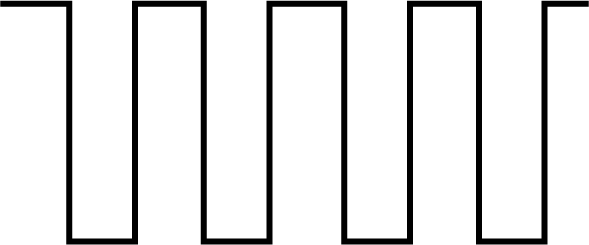
We could try to go to the next instruction when the clock goes either the its maxiumum (also called high, or $1$) or its minimum (called low or $0$), but that wouldn’t actually be a great idea. We haven’t covered it yet, but a computer isn’t like a human… at least not yet. The instructions it executes have to be stored somewhere and the CPU has to go and get the current instruction before it can execute that instruction. You might think that’s a weird notion, but the reality is that it will always take some time to perform any kind of operation in any CPU.
It’s easy to gloss over the operation “get the current instruction” as being instaneous and itself not really an operation at all, but in the land of computers, Nothing (with a capital N) is instantaneous. Everything must be accounted for because our Theoputer is running so fast that even things that seem like they happen instaneously may not make the deadline. So to execute any instruction on the list above actually takes two operations:
- Get the current instruction from the list
- Execute that instruction
If we were to write this all out, the actual list of instructions for the Theoputer would be:
- Get instruction $0$
- Execute instruction $0$, which in this case says: “Remember the number 4”
- Get instruction $1$
- Execute instruction $1$, which in this case says: “Remember the number 5”
- Get instruction $2$
- Execute instruction $2$, which in this case says: “Add the two numbers you’re remembering together”
- Get instruction $3$
- Execute instruction $3$, which in this case says: “Remember the result”
The more pedantic we are at this stage the happier we’ll be. Turning back to the clock, we could execute each of the list operations above on either the maximum or the minimum clock point. That would be fine. But we can cheat a little. Each transition of the clock (from min to max, and max to min) is easily detectable in logic circuits. So, let’s just decide that the “getting of instructions” will happen on the transition from max to min, and the execution of whatever instruction we got will happen on the transition from min to max:
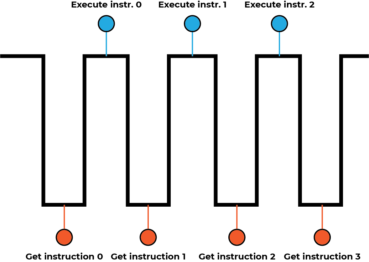
We can worry about the details of how this “getting instructions” and “executing instructions” works in the real Theoputer when we discuss the fetch-decode-execute cycle, but for now our goal is to design a circuit that can produce that beautiful square wave above.
A More Accurate Clock Diagram
The very astute reader may note two things about this. First, we’ve hammered on this notion that nothing happens instantaneously and yet the graph above shows an instantaneous jump from the min to the max value. Second, the lines indicating when actions are taken seem to be in the middle of the waves, but how?
More accurately, this is really what’s going on:
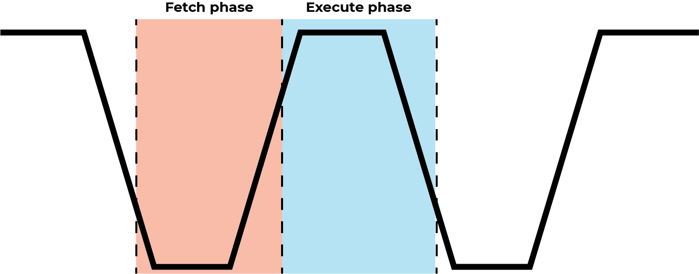
There is a finite transition time from the min state to the max state and there are really clock phases. You’ll note also that the blue phase starts at a different point than the orange phase. This is due to physical properties of the underlying semiconductors! In the Theoputer we are moving towards almost all logic chips being the CMOS (Complementary Metal-Oxide-Semiconductor) variety over the older TTL (transistor-transitor logic) variety. The properties of CMOS semiconductors are such that a “low” voltage or $0$ signal is usually around 0.8V and a high/$1$ voltage is usually very close to the supply voltage of the circuit, which is 5V in our case. Thus, when the clock transitions down to about 1.5V, the chips in the Theoputer (hopefully) see that as a transition from high to low, and when the clock transitions above about 3.5V the chips will see a transition from low to high. Normally it’s not necessary to model the clock in this kind of detail, but sometimes it’s absolutely necessary.
Oscillators
It’s unfortunate that starting to build a clock isn’t really an exercise in starting with first principles and building up. In theory we could go through all of the math around waves and circuits and oscillators. That would be a lot, to be honest. Instead, we can skip to the engineering part. We need a clock signal, and we ideally want it to be a square signal. Now there is no such thing as a true square wave (read all about that in the section on Transmission Lines). So our goal will be to get as close as possible.
There are many ways to build a square wave generator. We will only cover two here. If we want to be jargon-y we could talk about “vibrators”, but that isn’t really helpful to start with. Instead, let’s just talk about things that oscillate. In particular, let’s look at two things that oscillate really well:
- An oscillator
- A 555 timer
Ok the first one feels a little cheap. Obviously an oscillator oscillates. But that’s good enough! We just need something to oscillate, and oscillators do it. But oscillators oscillate at a specific frequency (usually), and while that would be fine in general, in the Theoputer we want to be able to do some good engineering work. That means we want to be able to control some of the system parameters as we develop parts of the system in isolation. One system parameter that will be invaluable to control is the clock frequency! So a regular old oscillator may be useful, but something that oscillates at a controllable frequency would be even better! And it turns out a 555 timer is a great option.
Controllable Oscillations
The 555 timer is a very cool and somewhat ubiquitous integrated circuit (IC). It’s uncommon that ICs go by their name like that, which underlines how ubiquitous they are. There are entire courses taught on the 555 timer. It’s very interesting, but too dense for our purposes.
There are wizards out there, Harry. Wizards who understand 555 timers like the rest of us understand words in a novel. There is one such wizard who wrote up a bunch of circuits, and that wizard’s website went defunct. But some awesome people build this Internet Archive and saved the wizard’s page on 555 Timer Circuits.
The relevant circuit on that website that we want is the “Better Timing” circuit. This is a reference design for a 50% duty cycle clock generated by a 555 timer. The duty cycle refers to the proportion of time spent in the high state versus the low state. 50% means there should be exactly as much time spent for the clock in its high state as it spends in its low state. Here is the image from that website:

And here is an implementation of that same circuit in the simulator.
Note: For fun I included the internals of the 555 timer (from the falstad circuit examples) so you can see it. You can also see where the timer gets its name – from the three 5k resistors in there. Though apparently that is in dispute.
This is a great place to start, not just because we need to start somewhere, but because adjusting the potentiometer (that’s R1 in the image, and on the left side of the circuit) will allow us to control the clock speed without affecting the duty cycle. Here’s the actual schematic of the first revision of the clock:
Apart from some (mostly) unrelated parts, you can see they are the same. The only part that’s worth pointing out is that in the Theoputer clock (though not in the most recent one) there are two adjustable modes: fast and slow. There are two capacitors C1 and C2 listed beside those two speeds. Those are there along with the switch to enable a very wide range of frequencies. Without the ability to switch between these two capacitors there isn’t a good way to engineer a clock like this that has a frequency range from ~1Hz to ~1MHz.
There’s actually a simple way to understand the range of these kinds of oscillators. Without going through the full derivation, the shortcut is:
$$ f = \frac{1}{1.1 * R * C} $$In our case in the limit, \(R=2\) and \(C_1=10^{-7}\). RV1 being 2 ohms is not quite correct, but it’s not really possible to know this minimum value without measuring the potentiometer in the circuit. Plugging those values in, we get:
$$ \begin{align*} f_{max} &= \frac{1}{1.1 * 2 * 10^{-7}} = 4,545,454\\ f_{min} &= \frac{1}{1.1 * 10^6 * 10^{-6}} = 0.909 \end{align*} $$It’s worth noting that the max frequency is only theoretical in this case. The 555 timer can only oscillate so fast due to the switching speeds of the internal components, so in practice this just let’s us hit the max frequency of the specific 555 timer chip we use. In the schematic above, that’s the LM555. It’s max frequency is 100KHz according to its Digikey product page, and they’re usually right, so we’re unlikely to get very close the max frequency with the circuit above.
The Other Oscillator - An Oscillator
Recall that there are many types of oscillators out there. For the Theoputer the most relevant ones are:
- An oscillator
- A 555 timer
Yes. An oscillator is a type of oscillator. The 555 timer we covered in the previous section, so let’s turn our attention to the other one: the oscillator.
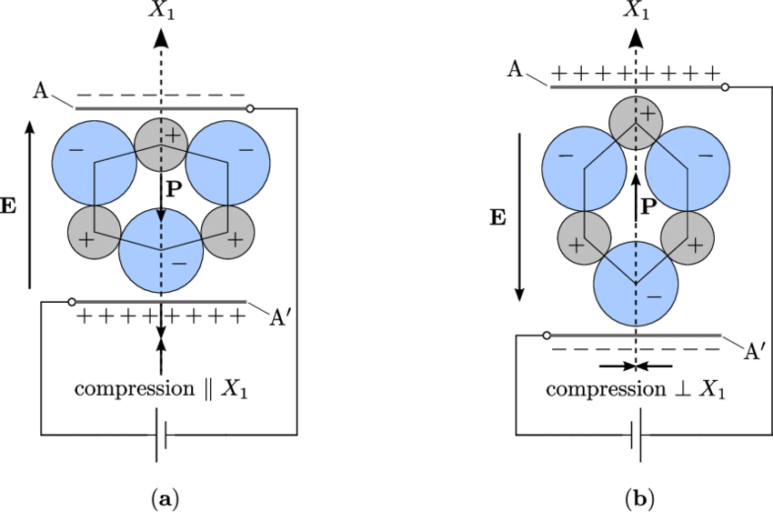
An oscillator of this form is comprised of a resonator and a feedback loop that stabilizes and amplifies the resonator so we can do things with the resonator. A common resonator you may be familiar with is a quartz crystal. It turns out, through something called the piezoelectric effect, if you physically squeeze (most) crystals you will induce a small voltage in the crystal lattice. This is due to the atoms of the crystal changing their bulk shape. This works in crystals because the definition of a crystal is that there is a repeated atomic structure. So if you deform the crystal in one direction, all of the repeated atomic structures deform in the same way.
For quartz, the repeated structure is a silicon atom and four oxygen atoms. Silicon and oxygen have different charge distributions (silicon has four valence electrons to oxygen’s six), different masses, and have different bonding energies between the Si-O and O-O bonds. So while a quartz crystal under no stress has a net charge distribution of zero, after squeezing or stretching the crystal the charge distribution will be lopsided and thus not net zero:
Note: I don’t know why the charge signs are switched in this image. Oxygen is more electronegative than silicon and thus should be more negative than silicon. Sometimes physicists and electrical engineers disagree on which sign electrons should get, so maybe that’s the reason.
This lopsided charge distribution creates an electric field, and thus an electric potential. Intuitively, any time there is a distribution of charges that is lopsided there is a potential to do some electrical “work”. If there were other charges near the positive side of that lopsided charge distribution they would move away! That is work.
The potential to do work, electrically, is called an electric potential and is what we colloquially refer to as “a voltage”. In summation, squeezing crystals makes a voltage. And because physics is cool and nature abides, that also means that applying a voltage across a crystal causes the crystal to squeeze.
We can exploit this two-way relationship to get a crystal into resonance. Based on the geometry and energies associated with the particular crystal lattice, there will be some resonant frequency where the crystal will most-easily squeeze and stretch. If we “simply” add in an amplifier to amplify this preferred frequency the crystal will produce a nice regular wave:
The circuit above looks simple enough, but underneath it is a complex balance of feedback and amplification. That complexity is wrapped in that component in the middle, which is an Inverting Schmitt Trigger. Inside that component is a op-amp, and inside the op-amp is a bunch of transistors. This is the land of wizardry. Perhaps another time we can go deep on those internals, but for now just know that an Inverting Schmitt Trigger is an amplifier that adjusts the phase of the output signal to be 180° offset from the input. That phase offset balances the one introduced by the capacitors at the bottom of the circuit so that the amplification is actually in-phase with the signal.
I want to be clear that I don’t know how this circuit works on a fundamental level. I’m sure I could figure it out if I spent enough time, but I just don’t understand analog circuits that well. And that’s ok! Engineering is sometimes an exercise in drawing mental boxes around things and just accepting that whatever’s in the box works. To use the thing in the box you just need to know what the inputs are (and their constraints) and what the outputs are.
Fortunately, we don’t have to implement this feedback and amplification circuit ourselves. Most of the time it’s the right decision to use an oscillator component. In the Theoputer we use a few different types, but the main clock uses either a 1.8432 MHz XO Can Oscillator in the older boards or a 1.8432 MHz XO SMD Oscillator in the newer boards.
Putting It Together
Here are the two clocks as they appear in the “Rev C” clock board:
You can see in this version that we’ve simplified the range of the adjustable clock based on the 555 timer to use a 1uF capacitor and a 10KΩ potentiometer giving a range of 454,545Hz to 91Hz.
There are some other features that are important that we’ve not covered. Namely the ability to step the clock ourselves manually and to control some of the clock aspects via the computer / instructions. Getting all of that working together is a bit more involved. Both because there’s more wizardry to come for the “debugger”/stepper logic, and because making the clock controllable by the computer for operations like reset and halt involves some logic. To avoid a marathon post, the details of those parts are covered in Clock Extras.