For now, this post will live without a lot of context. I am in the process of (attempting to) documenting the entire Theoputer journey and architecture, but I didn’t start out with that as a goal so for the time being some of this content may not make the most sense.
Introduction
In the Theoputer V4 there is no IRQ. This is ok, but it does limit some of the things we can do. Perhaps more importantly, all “modern” CPUs rely heavily on interrupts. That’s no coincidence. Interrupts are very useful. If we want our CPU to know that it should respond to some external “thing”, then we have two options:
- At some interval we poll a signal and when that signal is at some predefined state (i.e. LO or HI), we take action
- We have the “thing” tell our CPU when it wants our CPU to take action
While the polling is, in most cases, the easiest to implement, it’s hopefully obvious that it will be slow and clunky in most cases. That’s because we really want the “thing” to push information to us. We don’t want to pull data from it. In cases where we want a push-like operation, we need some way for the “thing” to interrupt the CPU on-demand.
This on-demand kind of interruption is exactly what and Interrupt Request is for. The name is painfully obvious.
The complexity here is about how the CPU can allow itself to be interrupted, correctly. In a polling situation, the solution is fairly easy to write down: after every N instructions, check some signal line and respond.
For interrupts, the solution is a lot more nuanced and ultimately more complex.
There is Always a Delay
One thing that eventually occurred to me is that there is always a delay between the interrupt request from the “thing” and the CPU.
That is, because, fundamentally the CPU chops up time into short blocks of time, based on the clock. The CPU cannot understand anything that happens inside those blocks, nor can it affect anything faster than those blocks.

Imagine that the “thing” wants to interrupt our CPU twice within that blue section of time. Well there’s nothing the CPU could ever do to satisfy both requests; the CPU is fundamentally limited by this speed.

In this case there is no hope for the CPU. It will always miss one of these interrupts. Which one will depend on the circuitry employed, but it must miss one of them because the CPU doesn’t understand events that happen this quickly.
How Much Delay?
There’s no way to fully prevent interrupt request processing delays, so how much delay will there be? I looked around to try to see what other CPUs do. The results of that search weren’t too rewarding. The first question to ask is whether we should interrupt what we’re doing as soon as possible or wait a little bit.
Naturally, you might say, stop as soon as possible. This is also what I had in my mind, but then I started thinking about the Instruction Microcoder. Theoretically the soonest we could be interrupted is at the next clock cycle. For reasons noted above, we can’t respond faster than that. But the next clock cycle is very likely not the next instruction, because every instruction is actually a sequence of micro-instructions. Each micro-instruction executes in a clock cycle, but an instruction may take as many as 16 clock cycles to execute in the limit.
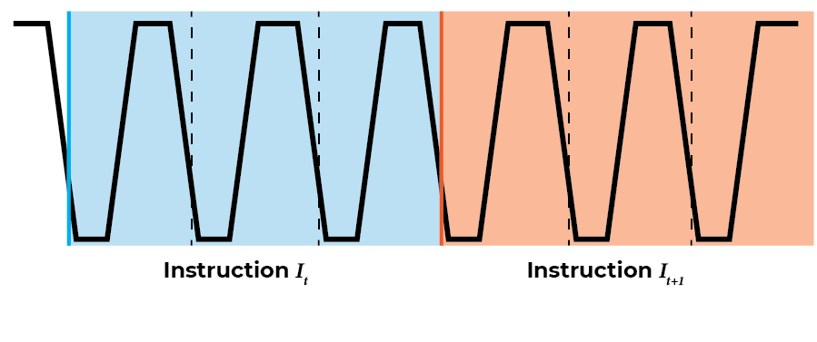
Here we have two subsequent instructions. What happens if the interrupt request comes in the middle of \(I_t\)?
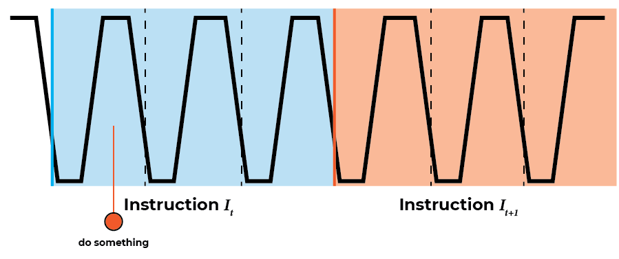
That is not illuminating, so let’s imagine that \(I_t\) is the instruction for copying a value from \(Reg_A\) to memory location \(Addr_t\). If it’s helpful, this instruction in the current assembly/ISA is MCA 0x00. This instruction is broken down into three micro-instructions:
- Copy the specified value (
0x00in the example) into the memory address register. - Output \(Reg_A\) to the data bus (DBUS) and connect the DBUS to the memory data input.
- Step the program counter.
If we look at the example of the interrupt request above, we see that the request comes after step (1) and before step (2) – note that the control lines that setup the operations listed happen on the down clock.
This might be ok for this instruction. We could just jump back to the start of \(I_t\) and run it again. But what if we have an instruction that changes some data inside the CPU on a temporary basis? Technically changing memory address register in step (1) is such a change. If some part of the interrupt handling code depends on the memory address register being set to a known non-intermediate value, then we would have a problem. That’s very unlikely in this specific case, but it’s almost a certainty for the very complex PSHA instruction (i.e. Push A to Stack).
So we cannot handle the interrupt as soon as it comes in. We must wait until we’re done with the current instruction. Then the CPU will be at a known good state (nothing intermediate). Once we are done with the interrupt handling code, we just need to jump to what would have been the next instruction.
What’s the Next Instruction?
We have to wait to handle the interrupt request until the next instruction, i.e. until the current instruction’s micro-instructions finish. But what is the next instruction? In many cases we could assume that’s just \(PC + 1\). But not all cases!
There are several instructions that perform jump-like operations (e.g. JMP, BEQ). If we’re in the middle of one of those instructions, we cannot assume the next instruction (after handling the interrupt) is \(PC + 1\). So we need to let the program counter micro-instruction happen first, then we save the program counter, and then we jump to the interrupt handler before the CPU actually executes the instruction in the program counter.
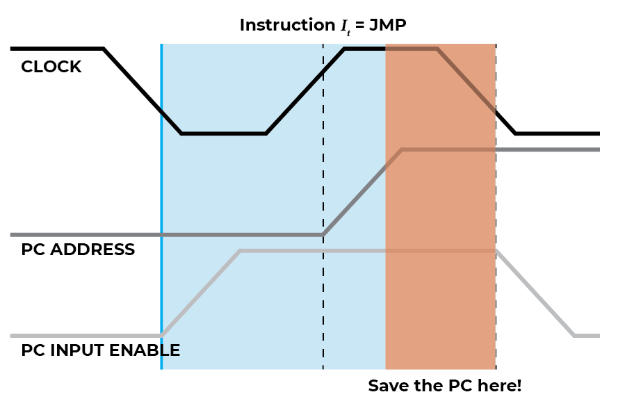
The JMP 0x28 instruction is a good one to consider (above), because it is only one clock cycle.
Note that
0x28is just an example, any value0x00-0xfffis valid for the JMP instruction.
On the down-clock phase the control lines are set. In this case (1)
the PC input control line is enabled to enable the program counter
(PC) to take input from the data bus (DBUS) and (2) the instruction
register output control line is set to enable the immediate value
provided in the JMP 0x28 instruction (0x28) to be output to the
DBUS. On the up-clock phase, the PC is loaded with the data on the
DBUS, thus setting \(PC_{t+1} = \textrm{0x28}\).
To return to the next instruction after the one that was executing when the interrupt request happened, we need to store the value of PC right before the next down-clock phase after the last micro-instruction of an instruction. Fortunately, there are only two such micro-instructions that do this, (1) either the PC step control line is enabled to ensure \(PC_{t+1} = PC_t + 1\) or (2) the PC input control line is set to ensure \(PC_{t+1} = DBUS_{t}\).
IRQ Stages
We now have the parts we need to put together the interrupt request (IRQ) functionality. But it’s helpful to think of the entire IRQ functionality as a sequence of steps. The word sequence here is doing some heavy lifting, because we truly need to do things in sequential order, with no possibility for parallelism.
Let’s start with a rough sketch of the stages:
- Detect a pulse on the IRQ line
- Wait for the current instruction to finish
- Save the next PC address to a safe place
- Inhibit the normal instruction execution loop
- Execute a special instruction to jump to the IRQ handler
- Execute the IRQ handler instructions
- Reset the IRQ circuitry
- Enable new IRQs
- Jump to the saved PC address from (3)
- Resume normal instruction execution loop
That is a lot of complexity. Too much complexity for me; it borders on cleverness and we should aim to “Never Be Clever”.
One notable part of the above stages is that 6-9 don’t need to be special compared to normal instructions we execute. That is of course assuming there are instructions that allow a programmer to control some of the noted “special” values. E.g. we would need an instruction to retrieve or jump to the PC value stored in step (3).
We can offload the complexity in 6-9 by relying on the “operating
system” to handle ensuring the correct instructions exist in the IRQ
handler. So if we pre-program our instructions such that at address
0x40 there is a sequence of instructions that perform steps 6-9,
then we needn’t worry about circuitry for those. That’s exactly the
assumption we’ll make. In effect, we are handling the IRQ in software
versus in hardware, and hardware is hard, so that’s probably a good
thing.
The new revised stages are:
- Detect a pulse on the IRQ line
- Wait for the current instruction to finish
- Save the next PC address to a safe place
- Inhibit the normal instruction execution loop
- Execute a special instruction to jump to the IRQ handler
- Resume normal instruction execution loop
Let’s look at each of these stages in turn.
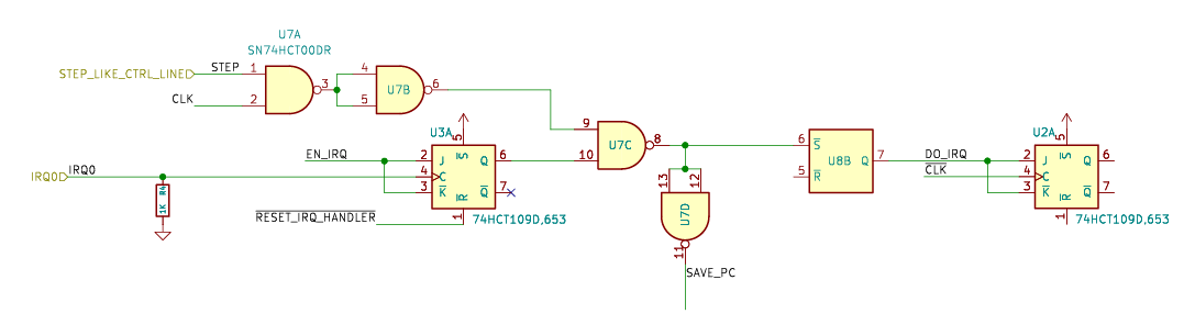
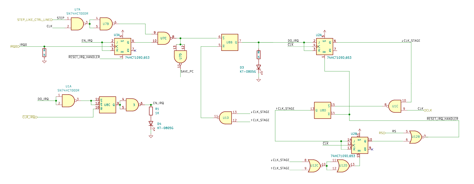
Stage 1: Detect IRQ Pulses
Normally when we want to “detect a pulse” we immediately think of a flip-flop. And this case is no exception to that. Flip that flop all the way to the bank.
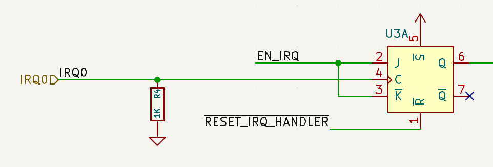
This is pretty straightforward. We’re using the IRQ input line as our clock signal, which will work nicely to debounce it.
There are a couple other signals in this part of the schematic, but
we’ll get to them in future stages. You can probably guess what they
do. The EN_IRQ line will be used to (re)enable IRQs to happen, so
it is connected to the J/K. The RESET_IRQ_HANDLER control line
is a LO-active line that resets the the IRQ circuitry, and thus needs
to reset this pulse “detector” as well.
The final note on this stage is the use of a pull-down resistor. Since we cannot guarantee that this IRQ will be connected to anything at all, we need one of these to guarantee we have a default signal, LO in this case.
Stage 2: Wait for Current Instruction to Finish
This stage is surprisingly (to me) simple because of the note that there are only two kinds of micro-instructions that indicate an instruction is complete: (1) the PC step control line is enabled to ensure \(PC_{t+1} = PC_t + 1\) or (2) the PC input control line is set to ensure \(PC_{t+1} = DBUS_{t}\).
If either of those lines is set (PI and PS specifically) and
we are in an up-clock phase, then we know the next down-clock will be
a new instruction. We saw that when we looked at the JMP
instruction in fact:
So for this stage we just need to detect this scenario:
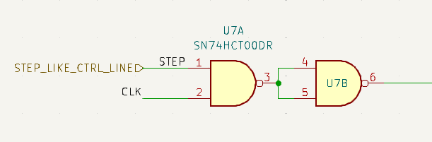
I’ve simplified this even more by forcing some other entity to tell this circuit that there is a step-like control line set. In theory that entity could be extended to handle other cases outside of the two current cases noted. #futureproofing.
Stage 3: Save the PC Address
We saw from the JMP example that as long as we wait to save the PC until the up-clock phase of the step-like micro-instruction, we’ll get the correct return address. There is some consideration/concern here around a race condition, because as I’ve drawn it to accentuate the delays / voltage ramp times, we technically have to wait a little longer than exactly when the up-clock phase happens to let the PC address become valid. But… that time isn’t too concerning because we have several gates that we have to go through before we save that address.
That’s four gates the signal has to go through. To be very certain, we can look at the delays for these gates (SN74HCT00):
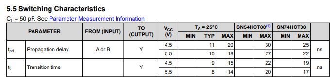
I’m not the best at reading these, but I think we want to consider the propagation delay, because we want to know how long it takes for a change on the inputs to reach the outputs: 10ns. That means the fastest these gates can ever respond to the input signals is 40ns. For the PC, we’ve used CD74HCT161s and their datasheet states:
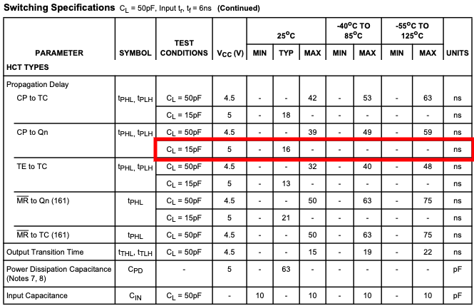
I’ve highlighted the row I ?think? matters. Again, these tables sometimes are very hard for me to interpret. In this specific case, it looks like we want to keep the PC pretty cool and reduce our load capacitance. I don’t have a good sense for what the load capacitance is… fingers shall remain crossed.
We need to store the PC address somewhere, of course, so we can jump back to it later. For that we can just use a plain old register. Two in this case because the registers we use are 8bit and the PC is 16bit.
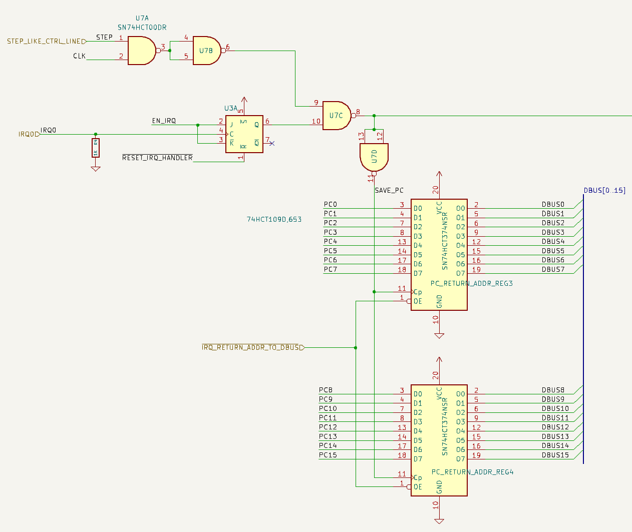
Here you can see our first new signal line:
IRQ_RETURN_ADDR_TO_DBUS, which we will need in order to jump
back to this saved address once we’ve processed the IRQ.
Stage 4: Inhibit Execution Loop
While we are executing our special instruction(s) to deal with the
interrupt request we need the CPU to avoid executing any other
instructions. I was compelled at first to take the “easiest” route and
think of a way to inhibit the clock or bring the HLT signal HI,
but none of those tricks really work because we need to execute some
instructions just not the ones that in the running program. So we
don’t want to mess with how the CPU is running, we just need it to
pause reading and executing from program memory until we’re done with
our special instruction(s).
The way we will achieve this is via three things happening in concert:
- Enable the IRQ processing stage
- Inhibit the Instruction Register altogether
- Inhibit the microcode counter
The first part will ensure we can signal to rest of the IRQ stages that they should proceed. (2) will make sure no instructions from program memory are loaded or used to set the control lines. (3) will make sure we aren’t advancing any micro-instructions, though this shouldn’t really be an issue.
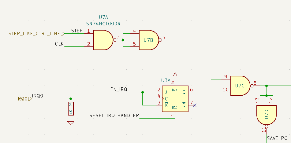
For (1), we already have this signal from when we detect that the PC is stable and loaded with the next instruction address. At that point we know we can process the IRQ. Imagine our IRQ handling logic was: do nothing. Then we would simply load the saved PC address back into the PC and carry on. From the CPU’s perspective nothing would be different. Thus, any non trivial instructions we execute starting at that point also look to the CPU as if we just jumped to some other function and jumped back.
At the moment when the PC return addressed gets saved we can save a bit that indicates we are in the IRQ processing stage(s):
Recall that this happens right after the CPU enters an up-clock
phase. Also recall that instructions are latched into the Instruction
Register, and thus the control lines are set, during the down-clock
phase. Since we want to execute a (special) instruction, we want to
detect that we just entered into the IRQ processing stages
(i.e. DO_IRQ is HI) and the next down-clock just happened:
This is an important moment to call out. This moment when the clock goes low is the moment when we need to disable the Instruction Register (IR), disable the microcode counter, and load our special instruction to jump to the IRQ handling code. Otherwise the CPU would effectively stall out. If we disabled the IR, the microcode counter, and didn’t load any other instructions, then the CPU will do exactly nothing. The only reason the CPU progresses at all is because either the microcoder counter increments (loading a new micro-instruction) or the PC changes (loading a new instruction). So it’s important that while we inhibit the normal execution loop, we simultaneously load our special instruction.
If you look at the original list of stages:
- Detect a pulse on the IRQ line
- Wait for the current instruction to finish
- Save the next PC address to a safe place
- Inhibit the normal instruction execution loop
- Execute a special instruction to jump to the IRQ handler
- Resume normal instruction execution loop
It’s actually the case that (4) and (5) happen at the same time. Really, they need to happen before the next up-clock phase, but we’ve designed our CPU to handle races within that timeframe so we’re good.
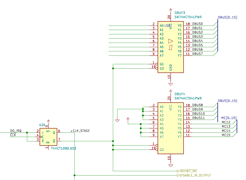
Stage 5: Execute the Special Instruction
While this happens at the same time as we inhibit our normal execution loop, the operation we perform is quite different.
As we argued earlier, it’s far simpler (and easier to change) if our IRQ handling is actually done in software versus hardware. That means we want to get to that software as quickly as possible, with as little circuitry as possible.
It’s a Bob Ross happy accident that it so happens the shortest instruction in our ISA is in fact a JMP, taking only a single clock cycle to execute. For some future proofing and flexibility we’re going to make the jump address definable in software as well. This will avoid needing to decide what that address is at fabrication time, which is a good thing.
Once again we’ll use a register for this and although the JMP instruction can technically handly up to JMP 0xfff, to avoid extra chips, we’ll just use a single 8bit register and force the IRQ handling code to be located in the first 256 bytes of the program. In fact, we could put another single instruction at that location to jump to some other, arbitrary address if we want. The sky’s the limit.
Here you see the addition of yet another control line:
IRQ_ADDR_SET. That’s the line that will need to be set LO to
load in the IRQ handler address from the data bus.
A quick refresher/note that we’re using NOR gates with the
CLKsignal, which creates a clock pulse on the up-clock transition. So this IRQ Address Register will be loaded in the up-clock phase in accordance with the very important principle that control lines are set in the down-clock phase, data is latched in the up-clock phase.
Now we just need to “simulate” a JMP IRQ_ADDR instruction. This is
not too complicated, especially because of the Bob Ross happiness. We
just need to tell the CPU to execute microcode instruction JMP
(0xf***) and provide the IRQ Address as the value in 0x***.
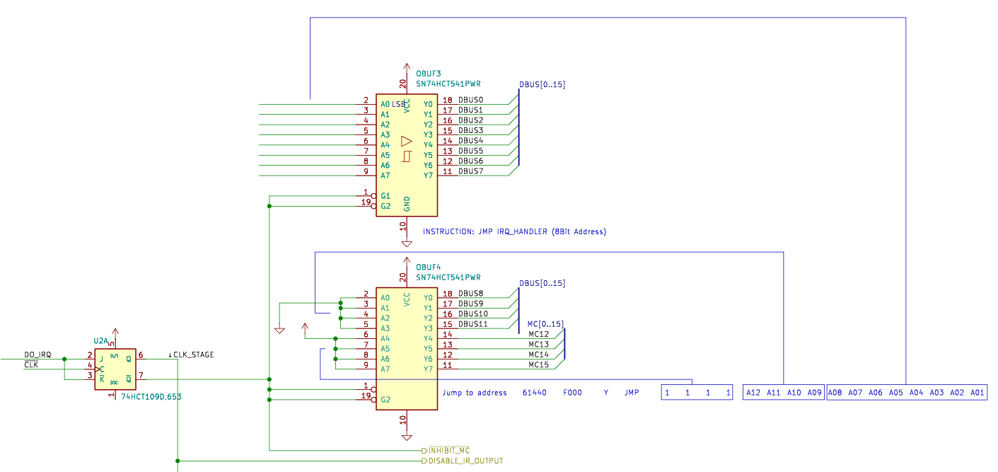
Just a quick note that the value
0xf***(1111 **** **** ****) above is only valid for ISAs that implement the JMP instruction with that specific value. If we were to change the ISA opcode of our JMP instruction, this circuit would not work. Perhaps a more future-proofed version would use DIP switches, but this instruction in particular feels stable enough to burn it into the board!
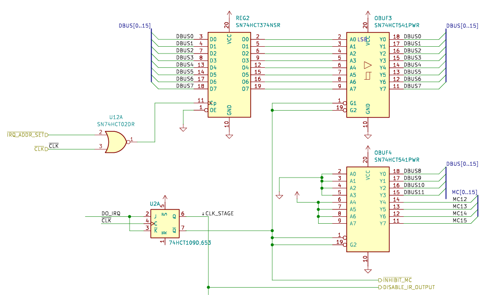
Step 6: Resume Normal Execution
At this point in the sequence we’ve inhibited normal execution and we just got the microcode instruction setup. That happened on the down-clock edge and the result is that (1) the microcode instruction chips will set the control lines of the CPU to prepare for setting the PC to the address on the data bus and (2) the data bus will contain the value in the IRQ address register.
We now have to “wait” through the up-clock phase. The PC actually changes/latches the input address during the up-clock phase. That’s as intended, because the PC is data and data is only allowed to be latched in up-clock phases.
The IRQ processing circuit doesn’t have anything to do in this up-clock phase except wait, but it does need to properly reset everything on the next down-clock phase so that the normal execution loop can take back over. This was surprisingly challenging to orchestrate correctly. Here is the circuit (for now):
Most of the challenge here is in avoiding race conditions. We need all of the IRQ processing signals to remain active for just the right amount of time, and then turn off in time for the next “regular” instruction.
There was a particularly nasty race condition that I discovered in the V1 circuit, which used only SR latches, that I documented in Modeling Reality is Hard.
Closing Thoughts
I knew interrupt request handling was going to be fairly challenging, but I underestimated the complexity. In particular the complexity around timing. It’s always timing that’s hard, sigh. I should have known that effectively trying to turn a sponaneous event into a well-timed sequence was going to be harder than it seemed.
Here’s a final graphic depicting the dance through the stages:

And here’s an oscilliscope capture showing that happening on the real board:

Next time we’ll explore the updates to the Instruction and Control board to connect up the IRQ, and then we can dig into some software for actually handling IRQs.
Ciao.