Introduction
It’s nice to start understanding the Theoputer here with the Arithmetic Logic Unit (ALU), which is really the only part of the computer that does much computation in the traditional sense. I remember being fascinated when I first learned addition could be encoded as a series of logical operations. It’s just such an incredible connection between two domains that are obviously related but not obviously interchangeable. This was the first “module” that I ever built for the Theoputer, and I did so first on a breadboard, before implementing it on a large PCB. Now my ALU is small, has no diagnostic lights, and supports many more operations than addition – it includes subtraction, shift left, shift right, bitwise AND, and bitwise XOR.
From Logic to Addition
At the heart of my ALU, and most ALUs you might learn about in school, is something called a half adder. This is a weird term. How can you half add something? It turns out this term is only useful if you know what a full adder is, so we’ll start there.
Back to Grade School
Let’s imagine we have just two numbers, represented in binary, that we want to add together. Similar to the rules of addition for decimals, represented as 10-digit numbers, we have some basic rules:
- Add the least-significant digits
- Carry over any amount above the digit limit to the next-significant digit
- Add the next significant digits and the carry
- Go to step 2 and repeat until out of digits
Here’s a simple example in decimal for adding 180 and 140:
  1 8[0]
+ 1 4[0]
-----------
      0
      (carry=0)

   [0] (carry)
  1[8]0
+ 1[4]0
-----------
    2 0
    (carry=1)

  [1] (carry)
  [1]8 0
+ [1]4 0
-----------
   3 2 0
   (carry=0)
That second step shows the carry in play. You did this automatically
in your head probably by now, but when you were first learning how to
add numbers you almost certainly had to this manually. In that second
step we have 8 + 4 = 12. But 12 is above the maximum digit in
decimal, which is 9. So we carry over the first digit, and leave the
second digit. In this case, we carry over the 1 and leave the 2
there. The carried over 1 gets included in the sum for the next-most
significant digit.
Binary Addition
The rules for addition in any base (binary, decimal, base-100) are always the same. You follow the same process:
- Add the least-significant digits
- Carry over any amount above the digit limit to the next-significant digit
- Add the next significant digits and the carry
- Go to step 2 and repeat until out of digits
Let’s try this with two binary numbers: 1011 and 0011. If you’re
just starting out with binary numbers, you can read all about
Base-N Numbers, or you can take my word
for it that \(1011_2 = 11_{10}\) and \(0011_2 = 3_{10}\). So we are
effectively adding 11 + 3 = 14. Let’s run our process just as we did
before with the decimal numbers 180 and 140, but this time, we
only have two digit possibilities: 1 or 0. In many ways this
simplifies things. There are only four possible combinations of two
base-2 numbers:
You may note, astutely, that when we get to a digit higher than the
least-significant one we actually will have a third digit to deal
with for the carry. However, that really only adds one more scenario,
which is when all three digits are 1:
Let’s try all of this with our numbers 1011 + 0011:
 1 0 1[1]
 0 0 1[1]
 -----------
       0
       (carry=1)

    [1] (carry)
 1 0[1]1
 0 0[1]1
 -----------
     1 0
     (carry=1)

  [1] (carry)
 1[0]1 1
 0[0]1 1
 -----------
   1 1 0
   (carry=0)

[0] (carry)
[1]0 1 1
[0]0 1 1
 -----------
 1 1 1 0
   (carry=0)
You’ll notice that the second step had that unique case when adding
three binary numbers of a non-zero digit and a carry. Our answer is
1110 in binary, which is 14 in decimal, just as expected. It
works!
Adders
Let’s break apart the two numbers we create in each step of our addition process. We have the output at digit position \(i\), call it \(o_i\), and the carry \(c_i\). Assume we have two inputs \(a\) and \(b\). How can we write down an equation in boolean algebra / logic that will give us the value of \(o_i\) as a function of the two digits \(a_i\), \(b_i\), and \(c_{i-1}\), recalling that we need to account for that carry. Let’s consult the table above:
$$ \begin{align*} 0 + 0 + 0 &= \colorbox{#ff0000}{0 \quad (\text{carry}=0)}\\ 0 + 1 + 0 &= \colorbox{#0000ff}{1 \quad (\text{carry}=0)}\\ 1 + 0 + 0 &= \colorbox{#0000ff}{1 \quad (\text{carry}=0)}\\ 1 + 1 + 0 &= \colorbox{#ff0000}{0 \quad (\text{carry}=1)}\\ 0 + 0 + 1 &= \colorbox{#0000ff}{1 \quad (\text{carry}=0)}\\ 0 + 1 + 1 &= \colorbox{#ff0000}{0 \quad (\text{carry}=1)}\\ 1 + 0 + 1 &= \colorbox{#ff0000}{0 \quad (\text{carry}=1)}\\ 1 + 1 + 1 &= \colorbox{#9900ff}{1 \quad (\text{carry}=1)}\\ \end{align*} $$This is a little too complicated at the moment. Let’s simplify things by noting that we need to perform the operation \(a_i + b_i + c_{i-1}\), which can be associated easily enough as \((a_i + b_i) + c_{i-1}\). But if we introduce a little stand-in number, call it \(s_i\) defined as \(s_i = a_i + b_i\), we see that now we’ve reduced things to only be sums of two binary numbers in sequence:
$$ \begin{align*} s_i &= a_i + b_i z_i &= s_i + c_{i-1} \end{align*} $$We still haven’t considered how to get the digit output and the carry from \(z_i\), but have simplified the total operation of adding three binary numbers to a sequence of adding two binary numbers. Let’s look at the table for that:
$$ \begin{align*} 0 + 0 &= {0} \quad (\text{carry}=0)\\ 0 + 1 &= {1} \quad (\text{carry}=0)\\ 1 + 0 &= {1} \quad (\text{carry}=0)\\ 1 + 1 &= {0} \quad (\text{carry}=1)\\ \end{align*} $$It sure looks like the digit should be result of XOR’ing the inputs and the carry should be the result of AND’ing the inputs:
| Input a | Input b | (a XOR b) | (a AND b) |
|---|---|---|---|
| 0 | 0 | 0 | 0 |
| 0 | 1 | 1 | 0 |
| 1 | 0 | 1 | 0 |
| 1 | 1 | 0 | 1 |
But we need to add another number to this! Before we do that, let’s recall that the carry is destined for the next digit. It cannot contribute to the current digit’s value. So if there’s any value coming out of \((a_i \; \textrm{AND} \; b_i)\) (that’s the carry), it doesn’t affect the next addition. In other words, only outputs of the \((a_i \; \textrm{XOR} \; b_i)\) operation need to be added to the \(c_{i-1}\). So we can write down the equation for \(o_i\) now:
$$ o_i = (a_i \; \textrm{XOR} \; b_i) \; \textrm{XOR} \; c_{i-1} $$Now the carry. Let’s start with an obvious case that produces a carry:
$$ c_i^1 = (a_i \; \textrm{AND} \; b_i) $$But there’s another way we could get a carry. If the operation \(a_i \; \textrm{XOR} \; b_i\) yields a 1 and the \(c_{i-1}\) digit is 1, we’ll also get a carry.
$$ c_i^2 = (a_i \; \textrm{XOR} \; b_i) \; \textrm{AND} \; c_{i-1} $$How can we combine these two results? Naively you could just add them together like we’ve been doing. But we don’t need to do that. Looking at the table above you’ll see that it’s not possible for \((a_i \; \textrm{XOR} \; b_i)\) and \((a_i \; \textrm{AND} \; b_i)\) to both produce 1. So either \(c_i^1\) is 1 or \(c_i^2\) is 1. Never both. Of course they could both be zero, but they can never both be 1, which means they can never produce their own “carry”. We don’t need to bother with all of the machinery to handle “proper” addition here because of this. We can just OR the results together:
$$ \begin{align*} o_i &= (a_i \; \textrm{XOR} \; b_i) \; \textrm{XOR} \; c_{i-1}\\ c_i &= [(a_i \; \textrm{XOR} \; b_i) \; \textrm{AND} \; c_{i-1}] \; \textrm{OR} \; (a_i \; \textrm{AND} \; b_i) \end{align*} $$Putting Together the Adders
We’ve gone through the details to get the equations for how to add two binary digits, accounting for carry:
$$ \begin{align*} o_i &= (a_i \; \textrm{XOR} \; b_i) \; \textrm{XOR} \; c_{i-1}\\ c_i &= [(a_i \; \textrm{XOR} \; b_i) \; \textrm{AND} \; c_{i-1}] \; \textrm{OR} \; (a_i \; \textrm{AND} \; b_i) \end{align*} $$These two equations, together, are called a Full Adder. I don’t really like the term Half Adder, which is where explanations tend to start, because my entire life before learning about adding binary numbers I never heard the term. It was too foreign to be useful. But if we know look at the equations above we can easily see that there is a repeated operation, namely that combination of two binary digits via an XOR and an AND. You’ll also note (though it’s not obvious) that those operations can happen in parallel.
This is hard to notice in the equation form, but much easier if we just draw out the logical schematic for this Full Adder:
Note: You can toggle the inputs on the right side by clicking the “L” labels, which stand for “Low Voltage”, and see how the two outputs change!
Notice in the schematic above we’re computing \((a_i \;\textrm{XOR} \; b_i)\) once and reusing it in both equations. Also notice the repeated XOR/AND combination in the first “stage” between \(a_i\) and \(b_i\) and then the output of \((a_i \; \textrm{XOR} \; b_i)\) and \(c_{i-1}\).
Apologies that the schematic uses “Cin” instead of \(c_{i-1}\). That’s a limitation of the circuit simulator, but other than formatting flexibility, this is my go to simulator!.
That repeated XOR/AND combination is what people call a Half Adder. Again, I don’t think that makes a lot of sense if you don’t know what the Full Adder is, but now that you do, it does make sense :).
Arithmetic Logic Unit
An Arithmetic Logic Unit can be many things. The simplest, and the first one in the Theoputer, is just a few Full Adders linked together. In the case of the Theoputer, since we are dealing in 8bit numbers, we have 8 such adders. Here are the first couple bits for easier reading:
The real schematic looks pretty much identical to that one, except for some headers to allow the ALU to be modularly inserted into other things. Initially the thing it was inserted into was a breadboard for testing. Once it proved to be working correctly, its destination was the Daughter Board.
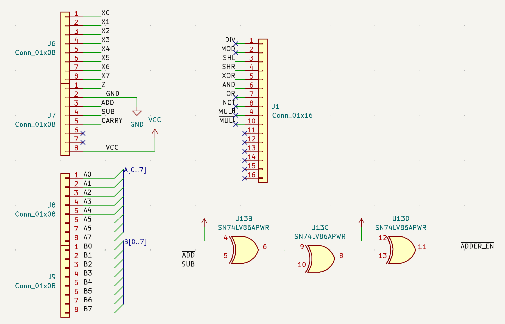
Note: Many of the control signals like
DIVhave an ‘X’ on them, indicating they are not connected and thus not used.
Other (Non-Addition) Operations
The ALU today, even as “fancy” by comparison as it is, is pretty much the same as the original ALU. It has a few more bells and whistles that allow instructions to pull out just the XOR result or just the AND result, with a couple other features. But other than that, it’s mostly the same.
There are two circuits that didn’t make it into the Theoputer, namely a circuit for Multiplication and Division. The reason they’re not in the Theoputer is because they’re too complicated (circuit-wise) and have too many chips in them to be worth it when we can just rely on the speed of the computer to repeatedly add or subtract things to “simulate” multiplication and division.
The one part of the ALU that we didn’t talk about that is in the Theoputer ALU is subtraction. The solution for subtraction is beautifully simple circuit-wise, but rather clever and non-intuitive (at first). If you want to know about that part of the ALU, the post on ALU Subtraction is what you want.