Introduction
When we covered Integrating IRQ0 it may have been obvious that there were a lot of synchronization issues to deal with. I certainly underestimated how challenging that would be. Going through one of the more subtle issues inspired the post Modeling Reality is Hard.
We’ll look at another issue that came up as I was writing the content for Integrating IRQ0, which made me appreciate this process of documentation that I have been rather loathe to do.
SR Latches Are Tricky
SR Latches are pretty simple devices, at least on the surface.
In our specific case we’ll see that there is some hidden complexity because our circuit is self-dependent. That is, the IRQ circuit’s state is dependent on the circuit itself. Specifically, the IRQ circuit is capable of disabling itself. And this is clever, but clever is something we should avoid. We should always Endeavor to Never be Clever™.
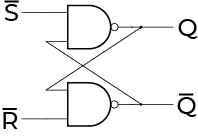
Let’s consider this part of the original IRQ circuit:
There is an issue with this circuit, but it’s very hard (for me) to
see. SR Latches are great, but they do suffer from one critical issue:
if both S and R are active at the same time, the state of
the latch is considered unstable. Well, that’s what any Internet
search would have you believe at least. Let’s evaluate the state of
the SR latch from above when both inputs are LO (active in this
case). Supposedly this is an unstable configuration:
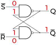
But that doesn’t appear unstable at all! Anytime one of the NAND inputs is LO, the output will be HI. The NAND gates themselves are not in an unstable state. They are very stable!
Stability isn’t the only issue we might encounter. While it’s arguable the current state is stable there are two other issues:
-
The complimentary output (
Qin this case) is supposed to be opposite the output, and it is not; they are both HI. -
If both
SandRchange to HI at the same time, there will be ambiguity about the state of the SR latch.
These are the reasons the Internet calls this configuration
unstable. Being a bit pedantic, it’s more accurate to say the
configuration is stable, but inconsistent and the simultaneous
transition to S=R=1 is an unstable transition.
In practice this means we have to be very careful when using SR
latches to avoid the two cases above. We can certainly use S=R=0,
but we should err on the side of avoiding it and if we are forced to
use it great care must be taken to use it correctly.
Timing Diagram for SR Latch
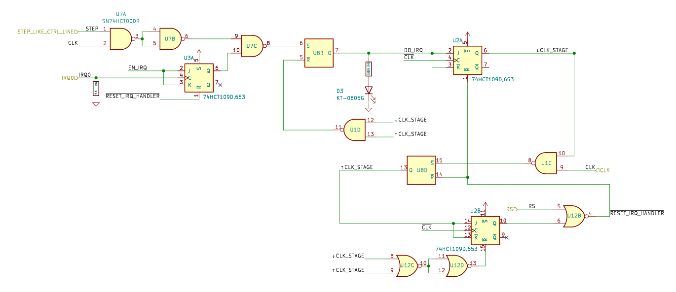
Reconsidering the original IRQ circuit:
There are two SR latches in this schematic. One is saving the state of
the ↑CLK_STAGE signal and the other saves the state of the
DO_IRQ signal. In effect, the two latches tell us what stage of
the interrupt request sequence we are in (see
Integrating IRQ0: IRQ Stages for details on that).
Let’s consider the timing diagram for the entire interrupt request. It’s fairly complicated, but in putting this together I actually discovered the issue this entire post is about. So while it’s laborious to work through these diagrams, they can be very useful for sorting out the challenging timing interactions of circuits, especially when there is self-dependence.
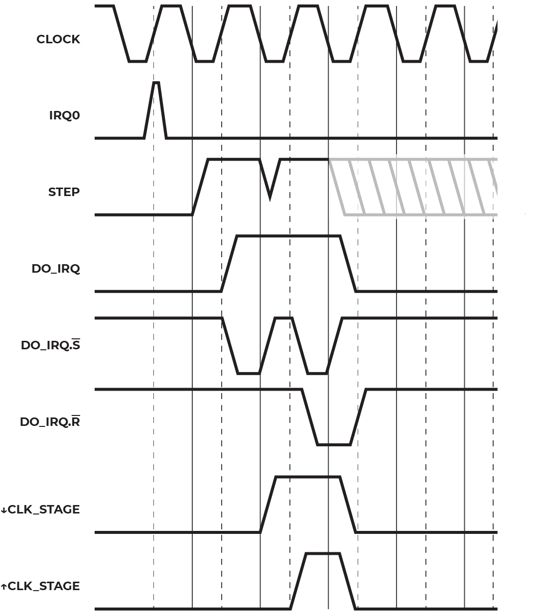
There is a lot to take in, and it’s hard to discuss the parts of this
in written word. The main part we want to look at, for now, is the
interactions between the clock stage signals and the SR latch for the
DO_IRQ signal.
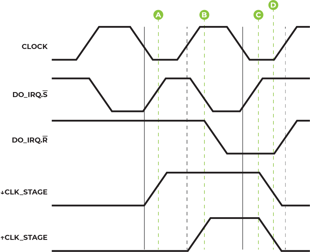
Starting from the bottom we see that there is a distinct
↓CLK_STAGE block starting at Ⓐ, following by a ↑CLK_STAGE
block starting at Ⓑ.
Note: Because of “hysteresis” in the gates/transistors and non-instantaneous transition times, the moment when a signal goes from HI to LO, or LO to HI is not a sharp boundary. We’re using a visualization here that is an approximation for the CMOS voltages, that is, LO is below ~0.8V and HI is above ~4V.
This simplified timing diagram doesn’t show the resetting signals, but we don’t need them to illustrate the problem here. Take a look at this region:
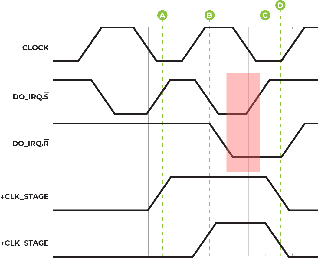
Both S and R are LO in this shaded block! That’s exactly
the situation that is unstable, according to everything you’ll read
about SR latches. Is this a problem for us? That’s not an easy
question to answer quickly. The quick answer, which is worth always
applying, is probably. And probably means just fix it, because
the cost of fixing it will almost always be less than the cost to not
fix it.
For argument sake, let’s look at an exaggerated and unlikely, but
possible, situation going on with the signal delays on the S
input and the R input:
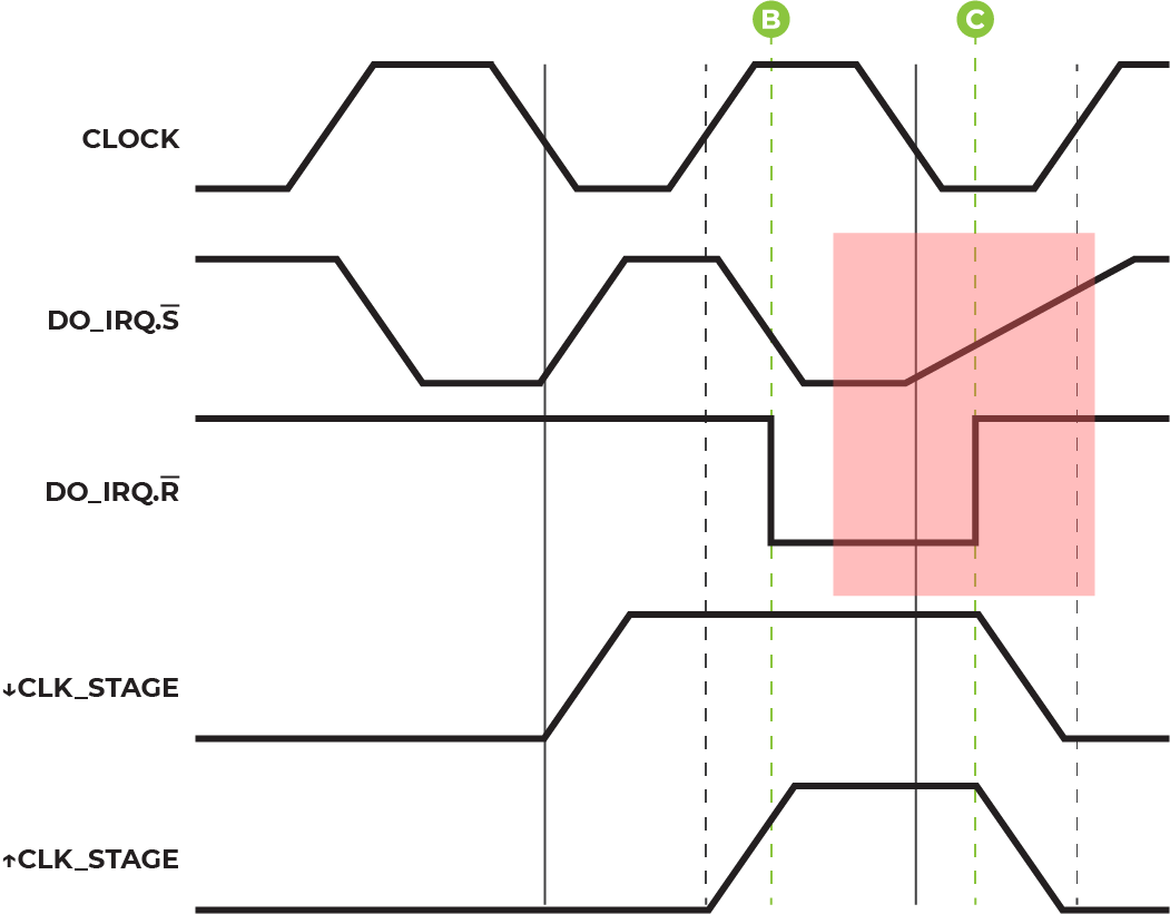
So now we have a problem! If S stays active too long, two bad
things can happen. Either S and R will race, and the
winner will set the output DO_IRQ. Or S is active so long
that it always wins out, and DO_IRQ stays HI after the interrupt
request! That’s definitely not correct.
The fix for this is to use a device that doesn’t suffer from this kind of issue, and for that we will use a JK Flip Flop.
Medium aside: My original fabricated circuit did use an SR Latch in the way described above. When I used a TTL-like gate (74HCT prefix) to invert the
CLKsignal, everything worked perfectly fine. However, when I inadvertently swapped that gate out with a CMOS-like gate (74HC prefix) I had this exact issue crop up. My best guess is the delay introduced in the CMOS-like gate, due to a higher voltage threshold for HI, caused a delay in the resetting signals. That delay was great enough in some, but not all, circumstances to cause the two inputs to the SR latch to race, asRwas connected to one of those resetting signals.
Fixing the SR Latch
When an SR Latch just won’t do the usual answer is a JK Flip Flop. And anytime I enjoy my flip flops I like to pair that with a nice Piña Colada🍹 (or Chi Chi if you want to be a bit more fashion forward), so treat yourself in kind if you are so bold.
The beauty of the JK Flip Flop is that it is clocked, so that it will only change on a transition from LO to HI or HI to LO, no matter what else is going on with the input signals.
Let’s zoom out mentally from our schematic for the interrupt request
and think about what it means for the DO_IRQ signal to be
active. That signal should really only ever be turned on when the
interrupt request first comes in. After that, the next thing the
DO_IRQ signal should do is turn off and it should turn off at the
point when we’re resetting our circuit.
In our circuit we almost have the condition we need. The interrupt
request signal IRQ0 definitely creates a LO -> HI
transition and then stays HI thereafter.
And funny enough that uses a JK Flip Flop! The other part of the
circuit that is faded out is also important. It ensures that we don’t
start handling the interrupt request via DO_IRQ until we both
received the signal on IRQ0 and we have just processed a
step-like operation. If you’re questioning why we need that, reread
Integrating IRQ0: What’s the Next Instruction.
Importantly, while there is only one time that the output of the
IRQ0 JK Flip Flop goes from LO to HI, the top part of the schematic
actually oscillates in time with the CLK signal, assuming we are
executing a sequence of JMP-like instructions. It so happens that
our interrupt request handling logic does in fact execute a sequence
of those operations, so we can consider the top of this schematic as
reproducing the CLK signal. That’s reflected in the timing diagram
if we look closely:
The DO_IRQ.S signal is tied to the output of the right-most NAND
gate and it’s clear that signal is oscillating from the diagram.
What that means is we can’t just rely on this one signal to be the input to the JK Flip Flop we will be adding in place of the old SR Latch.
The real condition we want to clock on is when both:
- There is a transition from LO to HI of the circuit above (i.e. the circuit that gives LO to HI transitions, with an ’s’, when there was an
IRQ0pulse and a JMP-like instruction was just executed) - We aren’t already in the
DO_IRQphase of interrupt processing
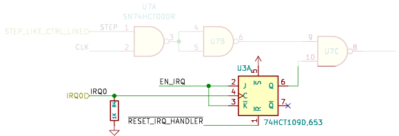
We could achieve that with some gates, but the JK isn’t just kidding! We can actually use its inputs a bit more intelligently and do this directly:
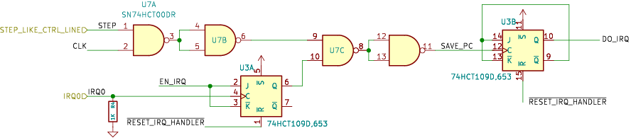
Just as advertised, we are using that JMP-like + IRQ0 signal
as the clock pulse. But notice that the other inputs to the JK Flip
Flop are being driven by the complimentary output of that same JK!
Talk about self-dependence…
In this case we want this connection. Let’s think about what’s
happening here. We can satisfy condition (1) above from the signal at
the JK’s clock input. Condition (2) states that we need to detect
whether we’re already in a DO_IRQ stage, and if so, ignore the
clock. Let’s look at the truth table for this JK Flip Flop, and pay
careful attention to note that the K input is inverted:
| S | R | CLK | J | K | Q | Q |
|---|---|---|---|---|---|---|
| 0 | 1 | X | X | X | 1 | 0 |
| 1 | 0 | X | X | X | 0 | 1 |
| 0 | 0 | X | X | X | 1* | 1* |
| 1 | 1 | ↑ | 0 | 0 | 0 | 1 |
| 1 | 1 | ↑ | 1 | 0 | Toggle | Toggle |
| 1 | 1 | ↑ | 0 | 1 | No Change | No Change |
| 1 | 1 | ↑ | 1 | 1 | 1 | 0 |
| 1 | 1 | 0 | X | X | No Change | No Change |
Spoiler Alert (Update)
Well it turns out the issue with the IRQ board was much deeper than what’s written about above. The issues detailed above are still valid, but they don’t appear to the be the root cause of the issues. The real cause seems to be in the instability of the clocking signal! Oh boy. Better rush over to the analysis of Transmission Line Reflections to learn about that proverbial enchilada.