Introduction
As I explained in the Theoputer Introduction, I started writing about the Theoputer pretty far along my journey building it. That means that:
- The order of posts is often weird
- I lost some context/information/etc. along the way
The first point is fine. The last point makes me sad. That last point is why I am forcing myself to do this laborious task of writing down a bunch of stuff I already went through. Well it’s that and for a kind of posterity that I hope to leave to the future little kids who are told they can’t do something because it’s too hard. But I digress.
I recently was going through my videos trying to find early ones of the Theoputer, and I scored! I wasn’t horrible at documenting some of the milestones I encountered in my journey after all. Phew. That’s out of character for me, but I’m glad for it this time.
The First Operation
If you’ve read about the Arithmetic Logic Unit (ALU) then you’ll know that a lot of the operations that a computer performs are some form of binary arithmetic. You would be forgiven for calling the ALU the “brain” of the computer. The brain of the brain perhaps.
It stands to reason that the first operation anyone might consider performing with a home-built computer would be an ALU operation. And here things are no different.
A slight difference is that the ALU was not the first circuit implemented in the Theoputer. That was actually the 8-bit register followed closely by the original clock. By the time the ALU was designed and fabricated these other two circuits already existed.
So here is a video of that very first operation, with a register and a clock in play. These are the oldest circuits built for the Theoputer and they are almost the size of the entire computer as it is today!
Video “Caption”
Rather than caption that entire video, let’s just go over what’s happening in case you don’t watch it all. We are performing the following simple operation:
$$ \begin{align*} \textrm{[Register]} &= (46_{10}) + (47_{10})\\ &= (93_{10}) \end{align*} $$It’s a little hard to see in the video, but the ALU has two 8-bit inputs on its left side, set via direct connections to VCC or GND to make the two input numbers:
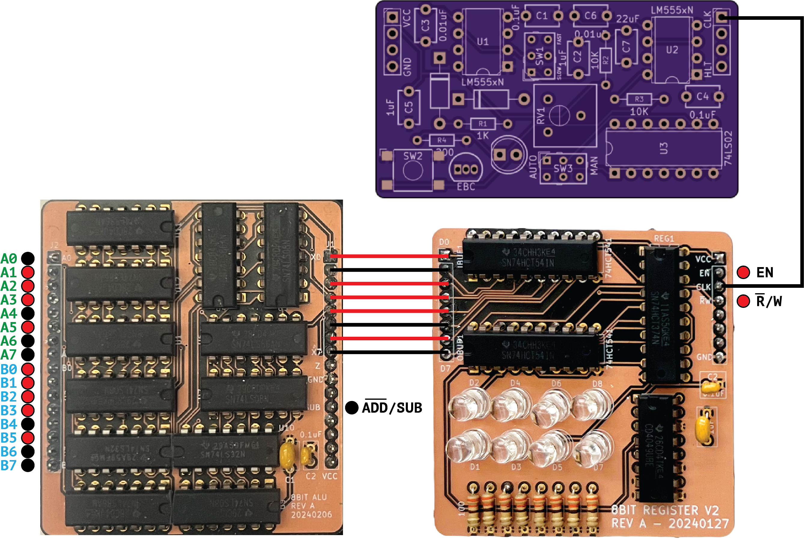
Since the CLK pin on the register is low, the register itself
doesn’t latch the data, but the ALU operates at the speed of the
gates, so its outputs are already set to \(01011101_2 = 93\) (MSB is
on the left). The clock then is manually triggered:
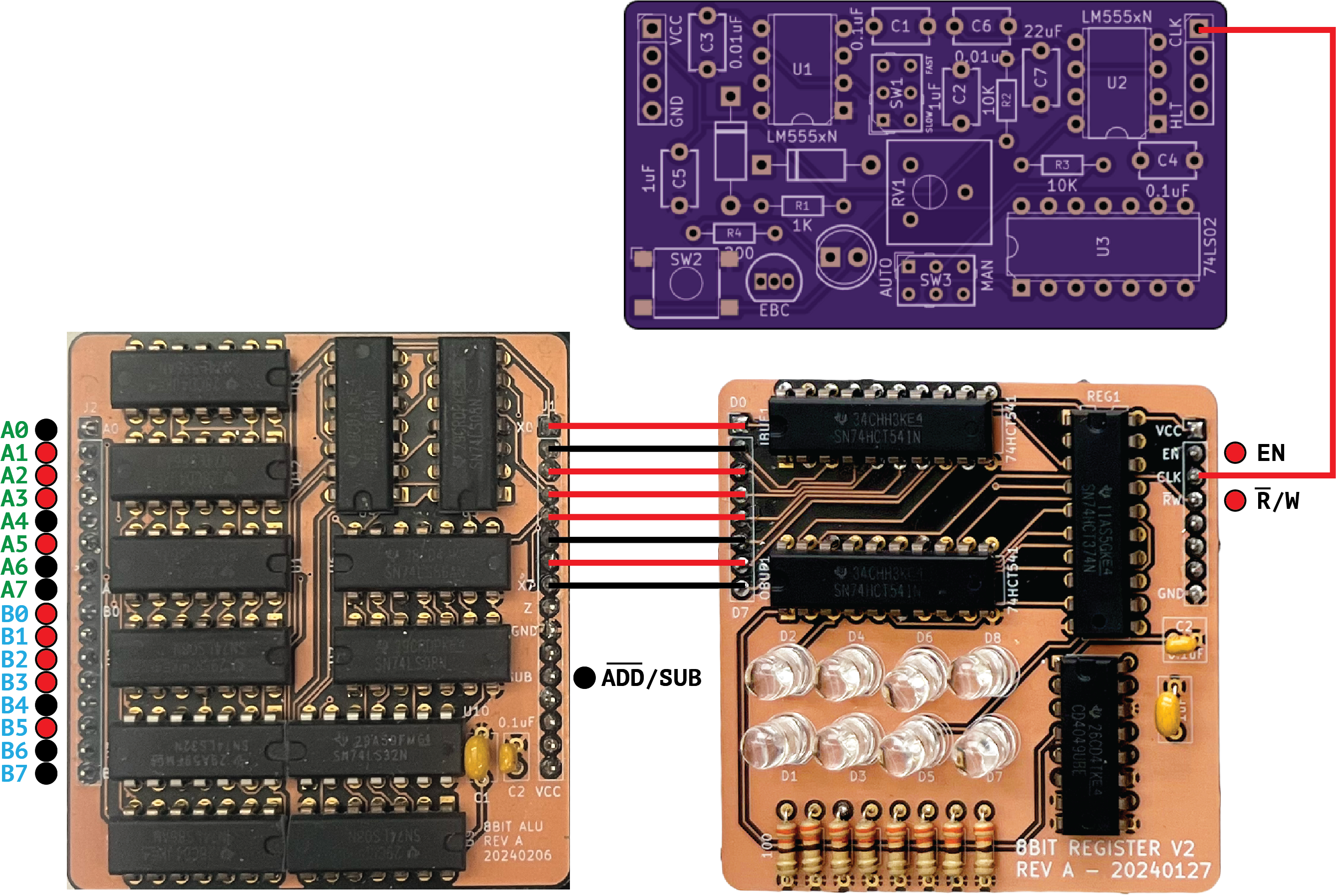
And then the register R/W pin is set to R (read), which
puts the register contents into the diagnostic LEDs:
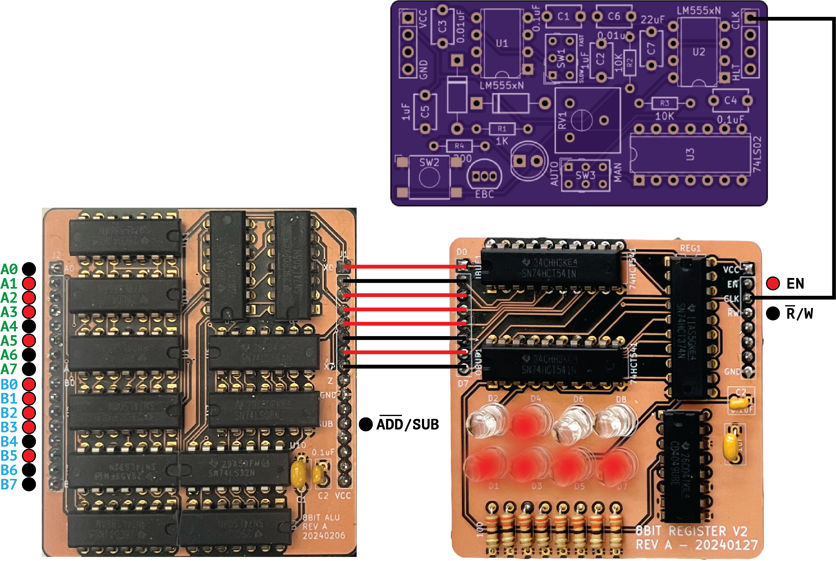
You’ll note a couple oddities with this whole sequence. First, the clock board above is clearly just a screenshot of the PCB. That is because I seem to have gotten rid of the actual physical board. Second, the register signaling is very odd, and in fact contains a major flaw that’s not readily apparent.
That said, this was the very first operation ever performed in the Theoputer, and it worked! From an engineering standpoint, the important part is that it was so barebones. That’s good engineering put into practice. Small, fairly isolated tests that can be used to gain insights on how to build the next version smarter, better, faster.