Introduction
I remember, long ago, when I first learned about how computers worked. I remember someone, I think it was Jason Mars who was a great friend and colleague, telling me about how they needed to do something interesting with the “program counter”. I was aghast. What do you need a counter for in a program? It just didn’t seem intuitive that you’d need to keep track of an incremented value, nor could it be that important.
Like many things, it took me a while to appreciate how important the program counter is. One thing that took me a while to really understand is that the name is not really indicative of its utility. It’s more of an instruction pointer or instruction address register. It points to the current instruction to be executed. In many, but absolutely not all, cases it is also incremented in a counting fashion. But branches cause it to jump all over the place. So maybe it’s my often too pedantic interpretation of words that was the issue.
Where are We?
Let’s say we have a bunch of instructions sitting on a ROM chip. We plug that ROM chip into a black box that knows how to turn those instructions into all of the signals needed to perform any instruction. We’ve also got a clock that will provided pulses that tell some part of our system to “move to the next instruction”:
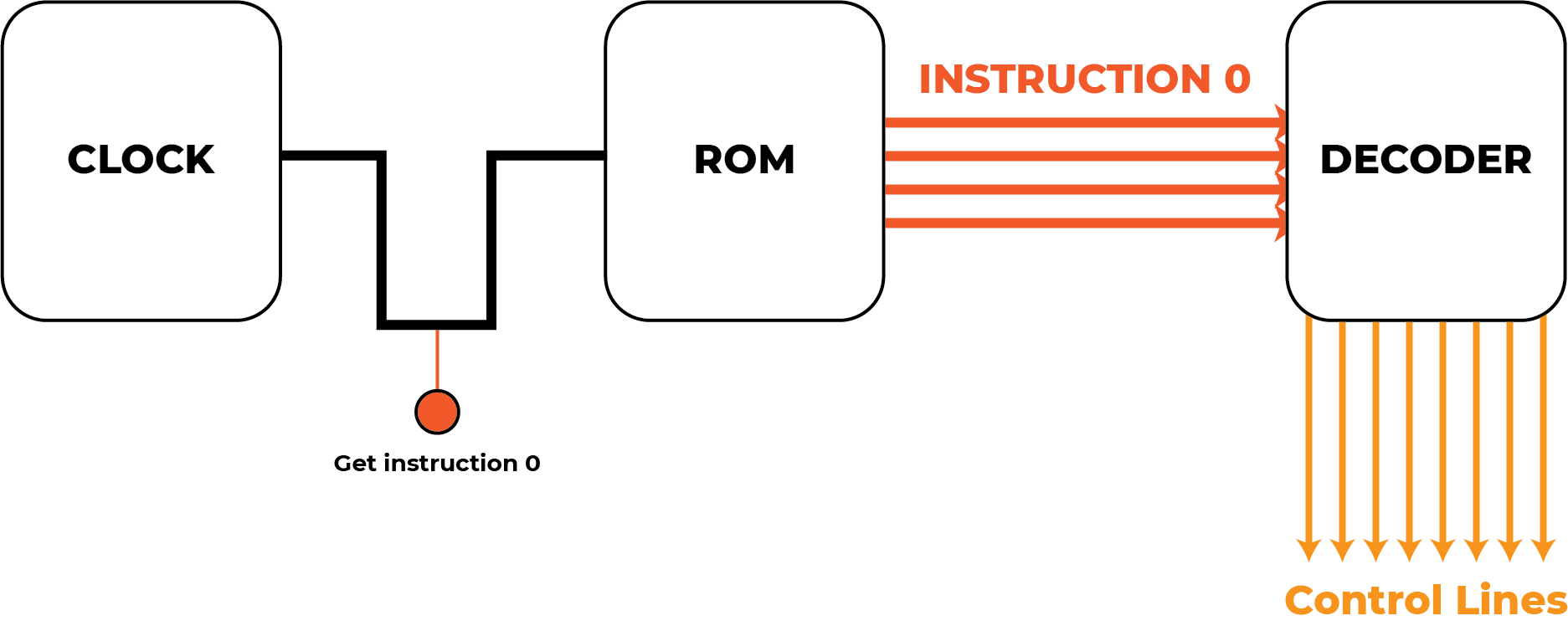
But you may notice a critical flaw here. How does a ROM chip take a clock signal and just know that it should output “Instruction 0”? Maybe when you first turn this device on the ROM internals are setup so that the default address is 0, but thereafter, how will it know what address to use?
Let’s take the real example of the Theoputer, which as of writing uses
the wonderful
SST39SF010
IC as ROM. If we consult the datasheet, we see that this chip
reads/writes 8 bits of data on pins DQ{0-7} and uses the value on
pins A{0-16} as the address to read/write from/to:

(Significantly more details are available in the post about the Instruction & Control board).
So we need something that can keep track of what address we need to pull instructions from. That is the program counter! The operation then looks more like this:
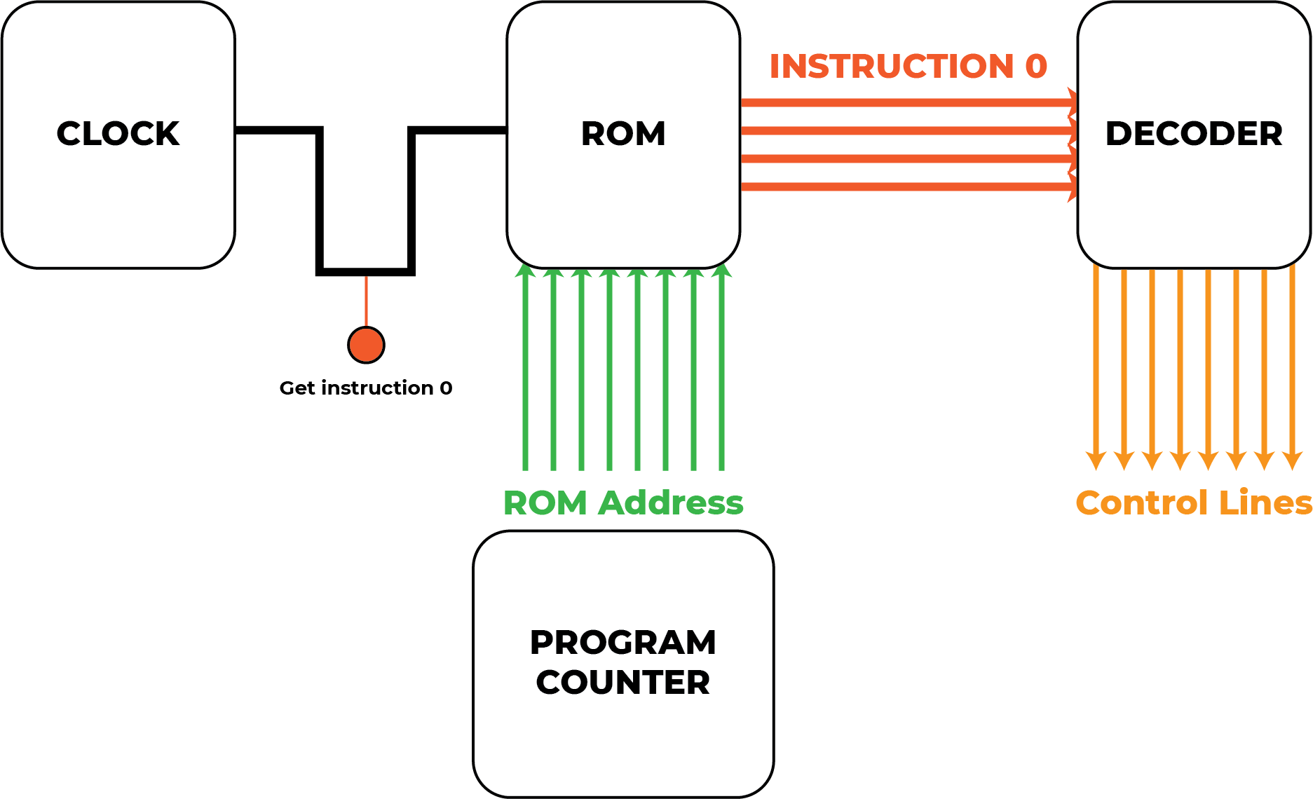
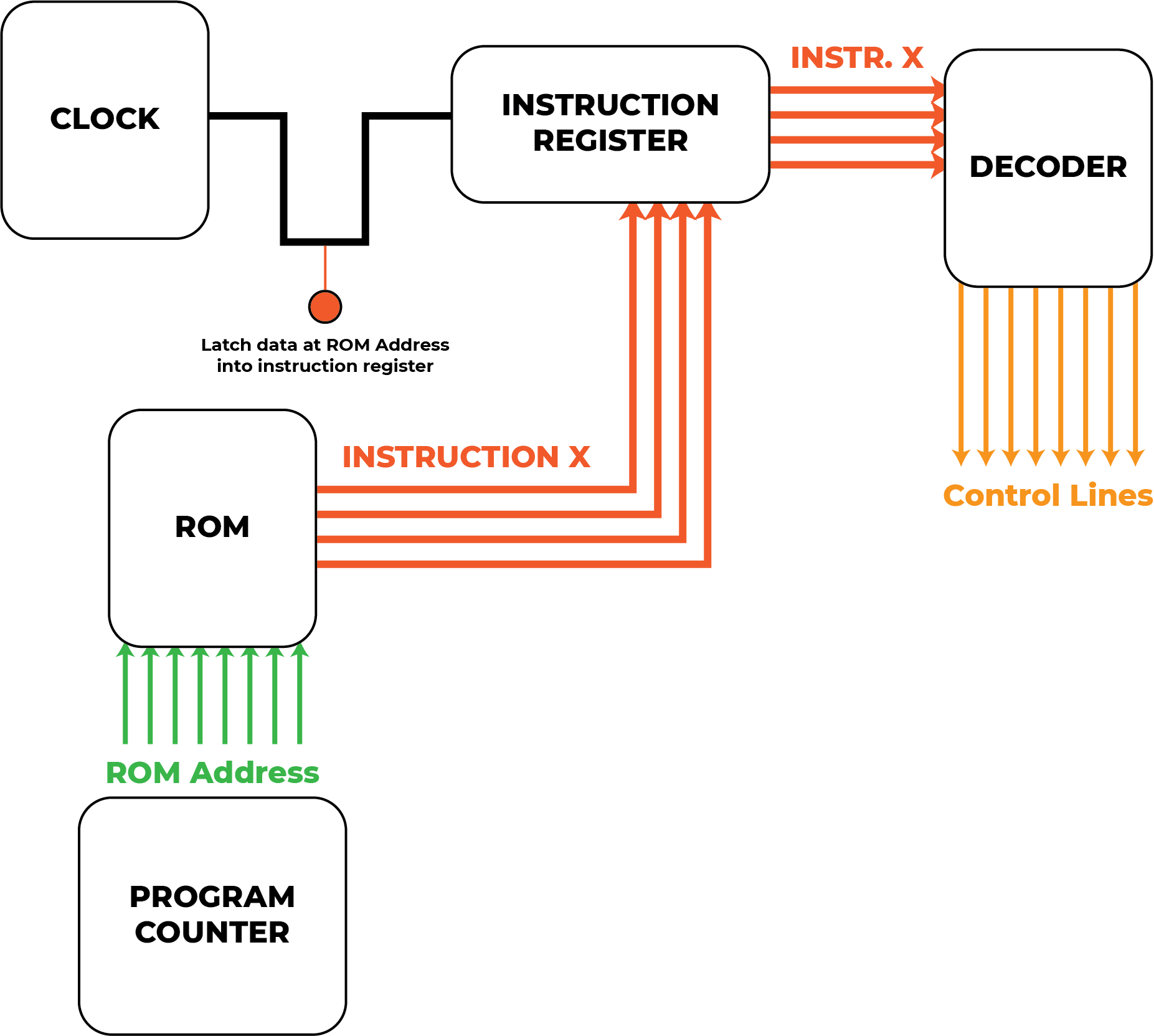
Ok, even that’s not exactly correct. The clock pulse is not used to indicate to the ROM chip to “Get instruction 0”. In fact, the clock pulse technically doesn’t interact with the ROM chip at all because the ROM neither controls the control signals nor does it affect the state of the computer. The true picture of what’s happening requires noting that there is an instruction register that holds on to the instruction while the operation is performed:
You might be tempted to call the program counter the “ROM address register”, but that (pedantically) excludes the notion of executing instructions from RAM.
What Is This Counter, Really?
As you can see from the more-accurate drawing above, the program counter’s job is to hold on to the address of the instruction to be executed. In that sense it’s more of an instruction address register.
Recall that the ROM chip we use in the Theoputer is the
SST39SF010. This
chip has 1Mbit of data storage, which is \(\frac{2^{20}}{2^{3}} =
2^{17} = 131,072\) bytes of data. That explains why that specific chip
uses the pins A{0-16}, as there are 17 address values available
for the 8 DQ{0-7} lines of data.
We have a choice at this point. Well we have many choices, but an important choice we need to make is to determine how many addresses we want to support. That is equivalent to asking how many instructions will the maximum number allowed for any program.
We could use the same register as the other registers in the Theoputer (SN74LV374 to be precise). But those registers don’t lend themselves well to being incremented. Despite the fact that the program counter can be set directly in cases where an instruction wants to jump to an arbitrary code location, many instructions will just execute their operation and then move on to the next sequential instruction.
So while a program counter is not just a counter, it does need to behave like one.
In theory we could use the ALU to perform the increment operation, but that would be a huge hassle. It would be an especially big PITA if we wanted to support more than 8-bits worth of instruction addresses as the ALU is only capable of directly performing operations on 8-bit numbers. That would mean all programs on the Theoputer would be effectively limited to \(2^8 = 256\) instructions long.
We could perform 16-bit ALU operations with the Theoputer’s 8-bit ALU, and in fact such operations are supported via the rudimentary “operating system” built in to the simulator and C compiler. However, it is quite expensive to perform those operations and we would need to hold on to the instruction while those other instructions executed. It would be a huge PITA.
But there is a better solution. Use a counter! Specifically, an integrated circuit (IC) that is made specifically to handle increment operations.
There are so many counters out there, where to start. The specific counter we need should have the following properties:
- Good at incrementing
- Don’t care about decrementing
- Need to be able to set the counter value to a specific, arbitrary value easily
That last criterion is often referred to as the counter’s ability to “load” or “preset”. Cutting to the chase, the specific chip we use in the Theoputer is the 74HC161. This is a 4-bit “up” counter (i.e. it’s good at incrementing) that supports “synchronous” operations (i.e. it can be clocked) and is “presettable” (i.e. we can set it to a specific value). Perfect!
Who’s Gonna Need More Than 256 Instructions?
The counter we’ve identified for the program counter is the 74HC161. It’s a 4-bit counter, and recall that the number of bits in the program counter dictates the maximum length of a program in the Theoputer. Technically we can have a program counter that is any multiple of 4 bits-long.
Let’s consider some of those values and also recall that our ROM chips support \(2^{17}\) addresses:
| Power of 2 | Decimal Equivalent |
|---|---|
| \(2^4\) | \(16\) |
| \(2^8\) | \(256\) |
| \(2^{12}\) | \(4,096\) |
| \(2^{16}\) | \(65,536\) |
| \(2^{20}\) | \(1,048,576\) |
The ROM chip we’re using doesn’t come in a version that supports \(2^{20}\) addresses, topping out at \(2^{19}\). We could use that version and just waste a bit, and that would be perfectly fine. At the end up the day it’s not much different to add another counter, but as of writing, the Theoputer uses four of those 4-bit counters, resulting in a total of 16-bits of addresses and thus supports a maximum of \(65,536\) instructions.
The Implementation
The actual circuit for these four counters is fairly straightforward, though the pin names are a bit odd:
There’s a standard interface to each individual chip that takes three control signals and the clock:
PS: When active the counters will step by one on the next↑CLKtransitionPI: When active the counters will takeDBUS{0-15}as input to their presets on the next↑CLKtransitionCLR: When active, will immediately set all counters to 0
Note: I can appreciate in retrospect that PS could be a great acronym for “Program Set” and PI a great acronym for “Program Increment”, but alas I didn’t think about that enough ahead of time and there are too many things that make the opposite assumption.
You can see another reason to use 16-bits worth of addresses, because that is also the number of bits available on the databus lines, which is how we set the program counter to a specific value.
Apart from the counters themselves and a little logic to handle the signals, the only other parts of the schematic are the diagnostic LEDs. These have proved invaluable in debugging the Theoputer, so they will likely stay forever. On the Daughter Board, the program counter lives in one area, with the diagnostic LEDs on one of the board edges to ensure they’re visible and not occluded by the Instruction & Control board that is plugged in to the Daughter Board in that area: